Since becoming a student at UC Davis, I have realized the importance of knowing where power outlets are so that I can plug my phone in... I spend a lot of time on my phone and it drains the battery rather fast.. I have since decided to build a solar cellphone charger. Now I know I could just go out and buy one, but: A: whats the fun in that & B: I have a problem with the chargers that are out there. They mainly charge your cellphone (or other USB peripheral device) from the internal battery.. which in turn gets charged from the solar cell. The problem with this is that you are required to leave the solar charger unit out in the sun sometimes for 6 or more hours. Now I don't know about you, but I think the sun gets pretty hot right? The internal battery of the solar chargers are lithium ion/lithium polymer batteries which are not supposed to be left in the heat of the sun or they can be destroyed (I made the mistake of leaving my ipod on the seat of my car... needless to say I killed that battery and it would only hold a charge for 20 minutes after that). Besides, the solar cells are small and charge the internal batteries up slowly...
So my theory is this: 3.5W solar cell connected to a boost/buck converter with voltage regulation and a USB output. The converter is capable of taking 3-30V and regulating it to a stable 5V which happens to be the voltage of the USB (notice I didn't say bus, because that would then be universal serial bus.. bus ;) ) The beauty of this is that as sun exposure changes and the voltage from the cell (actually an array, or panel) will drop, but the output on the USB will remain at 5V, just at a lower current. This bare bones charger will be housed inside a custom acrylic enclosure. Pictures will come once all the parts have come in the mail.
Monday, October 10, 2011
Sunday, October 2, 2011
Eastwood Versa-Cut Plasma Cutter
Recently Eastwood company has come out with their 'own' affordable plasma cutter. At a $600 price tag the deal seems almost too good to be true. Unfortunately there are a lot of cheap Chinese plasma cutters out there right now (a quick search on ebay shows many of them) like the lotos, longevity, simadre, logos, cut 40, cut50, etc. Well... Eastwood has claimed that they their product manager/inventor Mark Robidoux has engineered and developed this plasma cutter to be versatile and highly effective. After purchasing, and using one multiple times I agree that it is very effective and the ability to switch between a 240/120V supply is nice. The infinite amperage adjustment, air pressure, and built in 'last stand' water separator are nice features. One of the best features however is the use of a nice torch with HYPERTHERM consumables, which makes it nice that you can run down to your local welding shop and pick them up. I have read mostly glowing reviews on the product, save for one (sparks flying from the front out the vent holes! Yikes!!) After researching plasma cutters for quite some time I finally took a gamble on the Eastwood and so far I have had no regrets. That said, after seeing the internals of many of the cheap plasma cutters I was determined to find pictures of the internals of the Eastwood model to compare to. The Eastwood cutter is made in China, like most everything else today. This doesn't necessarily make it a bad thing, as a lot of Chinese electronics are of good quality, but it concerns me as to the quality of the internal components. I know that most of the cheap Chinese units fail because something inside shorts the MOSFETS out, or wires come loose, or screws come loose, or even the spark gap that controls the HF start circuit is not adjusted right... Well, because of my stubborn-ness and curiousity I committed the unspeakable crime of OPENING THE UNIT UP!!!! I believe these are the FIRST pictures to hit the web of the insides of this unit.


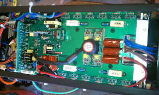


 Upon opening, I can't give Eastwood all the credit for the design of this machine... Some of its electronics look very similar to some of the nicer plasma cutter innards, but some of them do look very similar to the CUT40/50 models (which are the cheap Chinese units that are just re-branded under countless names) as well. Here are some differences: First off, there is no spark gap for the HF arc (that I could find) which is a common problem with the cheapies. And secondly, every connector is HOT GLUED in its place so that they don't come undone. This makes me happy, as most of the problems with the overload on the cheapies comes from connectors becoming dislodged or bad connections. All of the solder joints look good to me (no cold solder joints) and there are several differences between the cheap units and the Eastwood unit toward the business end of the machine. The air solenoid looks much more durable to me as well. I have made quite a few cuts with this unit; some short cuts through thick steel and some long cuts through rusted 55 gallon drums. I haven't had a problem with it at all, and I very much like Eastwood's warranty on it. Although.. I probably just voided mine by opening it up ;).


Saturday, July 2, 2011
Harbor Freight/Chicago Electric Welder 90A modifications
So all done with modifications. Installed a 1200V 150A bridge rectifier (i know its overkill but it'll survive any transients and voltage spikes). I placed a 22,000uf capacitor on the output which helps smooth the DC. Because of the bridge rectifier, the voltage is a bit higher than it was before. This seems to give a slightly hotter weld. It definitely has more penetration but the problem is because its flux core it still splatters like hell.
Monday, June 27, 2011
Harbor Freight/Chicago Electric Welder 90A modifications
So I installed a fan the one side to keep the welder cooler and increase the duty cycle. Next step is adding bridge rectifier, capacitor, and various voltage spike protection.


Friday, June 24, 2011
Coilgun update
So update on the coilgun with some pictures. Charging circuit is done. I used Uzzor's modified Mazzili driver
To charge the capacitor banks to 375V. I got this idea from Jason's 1.25kj coilgun. Actually his coilgun was the inspiration for mine. Things I'm doing a little differently are: 3 stages (2 optically triggered) with less energy per capacitor bank, shorter slug about .30 caliber, a 14.4V 2100mAh NiCd battery instead of his 12V NiMh. I will also have a bolt mechanism like a rifle to position the slug in the initial coil. All cap banks will have to be charged separately due to not wanting them hooked together when firing so a switch will separate them. The optically triggered stages will be designed based on the time the slug is in the coil determined by initial velocity (from the previous coil) of the slug. This should make the coilgun much more efficient and achieve a greater final velocity. Stage 1 will have only about 1000uF capacitor bank while the following 2 stages have a 4800uF bank. All capacitors are charged to 375V which is 75% of the working voltage of these capacitors. More theory and details to follow but as for now, some pictures of the coil winding, capacitor bank building and the battery pack building.


Tuesday, June 21, 2011
Harbor Freight/Chicago Electric Welder 90A modifications
When striking an arc with the wire, the wire feed motor suffers from a temporary slowdown as the current draw is large for the weld and the voltage sags for a second at first. The power for the wire feed comes from the secondary of the main transformer. It's no load voltage is around 24 something volts AC. Once an arc is struck the voltage goes down significantly. The first idea was to place a capacitor on the output of the bridge rectifier on the motor control board. This resulted in the motor remaining on after the trigger was pulled and not turning off. Must have had something to do with how they control the motor speed... my second idea was a series inductor in line with the motor and it WORKED. You don't want a capacitor across the motor because it will slow down startup and make the motor run longer after the trigger is released. With a series DC inductor in line with the motor it helps to provide constant current to the motor when an arc is first drawn. I wound the inductor on a ferrite toroid from a atx psu. It's wound with 20ga wire and measures around 120uH. It's a simple fix and the first of a series of fixes to the Welder.

Harbor Freight/Chicago Electric Welder 90A modifications
So many of you probably have this cheap flux core welder from Harbor Freight. It welds a million times better after switching from the cheap hf wire to Lincoln, but it still leaves a lot to be desired. After quick inspection I discovered that the Welder outputs AC. Anyone that knows anything about flux core welding knows that the electrode should be negative polarity in order for a good penetrating weld and little spatter. I have decided to rectify and filter the output of this Welder in order to make it into something better than just a cheap entry level Welder.
This website has proven instrumental in helping me convert my Welder.
Subscribe to:
Posts (Atom)